Expansion#
Expansion Connectors#
The expansion interface on the board is comprised of two 46 pin connectors, the P8 and P9 Headers. All signals on the expansion headers are 3.3V unless otherwise indicated.
Note
Do not connect 5V logic level signals to these pins or the board will be damaged.
Note
DO NOT APPLY VOLTAGE TO ANY I/O PIN WHEN POWER IS NOT SUPPLIED TO THE BOARD. IT WILL DAMAGE THE PROCESSOR AND VOID THE WARRANTY.
NO PINS ARE TO BE DRIVEN UNTIL AFTER THE SYS_RESET LINE GOES HIGH.
Figure ? shows the location of the expansion connectors.
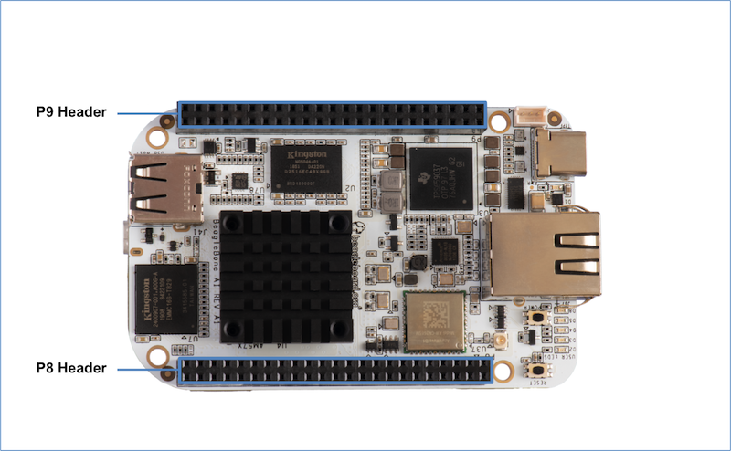
The location and spacing of the expansion headers are the same as on BeagleBone Black.
Connector P8#
The following tables show the pinout of the P8 expansion header. The SW is responsible for setting the default function of each pin. Refer to the processor documentation for more information on these pins and detailed descriptions of all of the pins listed. In some cases there may not be enough signals to complete a group of signals that may be required to implement a total interface.
The column heading is the pin number on the expansion header.
The GPIO row is the expected gpio identifier number in the Linux kernel.
The BALL row is the pin number on the processor.
The REG row is the offset of the control register for the processor pin.
The MODE # rows are the mode setting for each pin. Setting each mode to align with the mode column will give that function on that pin.
If included, the 2nd BALL row is the pin number on the processor for a second processor pin connected to the same pin on the expansion header. Similarly, all row headings starting with 2nd refer to data for this second processor pin.
Note
DO NOT APPLY VOLTAGE TO ANY I/O PIN WHEN POWER IS NOT SUPPLIED TO THE BOARD. IT WILL DAMAGE THE PROCESSOR AND VOID THE WARRANTY.
NO PINS ARE TO BE DRIVEN UNTIL AFTER THE SYS_RESET LINE GOES HIGH.
P8.01 |
P8.02 |
|---|---|
GND |
GND |
P8.03 |
P8.04 |
P8.05 |
|
|---|---|---|---|
GPIO |
24 |
25 |
193 |
BALL |
AB8 |
AB5 |
AC9 |
REG |
0x179C |
0x17A0 |
0x178C |
MODE 0 |
mmc3_dat6 |
mmc3_dat7 |
mmc3_dat2 |
1 |
spi4_d0 |
spi4_cs0 |
spi3_cs0 |
2 |
uart10_ctsn |
uart10_rtsn |
uart5_ctsn |
3 |
|||
4 |
vin2b_de1 |
vin2b_clk1 |
vin2b_d3 |
5 |
|||
6 |
|||
7 |
|||
8 |
|||
9 |
vin5a_hsync0 |
vin5a_vsync0 |
vin5a_d3 |
10 |
ehrpwm3_tripzone_input |
eCAP3_in_PWM3_out |
eQEP3_index |
11 |
pr2_mii1_rxd1 |
pr2_mii1_rxd0 |
pr2_mii_mr1_clk |
12 |
pr2_pru0_gpi10 |
pr2_pru0_gpi11 |
pr2_pru0_gpi6 |
13 |
pr2_pru0_gpo10 |
pr2_pru0_gpo11 |
pr2_pru0_gpo6 |
14 |
gpio1_24 |
gpio1_25 |
gpio7_1 |
15 |
Driver off |
Driver off |
Driver off |
P8.06 |
P8.07 |
P8.08 |
P8.09 |
|
|---|---|---|---|---|
GPIO |
194 |
165 |
166 |
178 |
BALL |
AC3 |
G14 |
F14 |
E17 |
REG |
0x1790 |
0x16EC |
0x16F0 |
0x1698 |
MODE0 |
mmc3_dat3 |
mcasp1_axr14 |
mcasp1_axr15 |
xref_clk1 |
1 |
spi3_cs1 |
mcasp7_aclkx |
mcasp7_fsx |
mcasp2_axr9 |
2 |
uart5_rtsn |
mcasp7_aclkr |
mcasp7_fsr |
mcasp1_axr5 |
3 |
mcasp2_ahclkx |
|||
4 |
vin2b_d2 |
mcasp6_ahclkx |
||
5 |
||||
6 |
||||
7 |
vin6a_d9 |
vin6a_d8 |
vin6a_clk0 |
|
8 |
||||
9 |
vin5a_d2 |
|||
10 |
eQEP3_strobe |
timer11 |
timer12 |
timer14 |
11 |
pr2_mii1_rxdv |
pr2_mii0_rxdv |
pr2_mii0_rxd3 |
pr2_mii1_crs |
12 |
pr2_pru0_gpi7 |
pr2_pru1_gpi16 |
pr2_pru0_gpi20 |
pr2_pru1_gpi6 |
13 |
pr2_pru0_gpo7 |
pr2_pru1_gpo16 |
pr2_pru0_gpo20 |
pr2_pru1_gpo6 |
14 |
gpio7_2 |
gpio6_5 |
gpio6_6 |
gpio6_18 |
15 |
Driver off |
Driver off |
Driver off |
Driver off |
P8.10 |
P8.11 |
P8.12 |
P8.13 |
|
|---|---|---|---|---|
GPIO |
164 |
75 |
74 |
107 |
BALL |
A13 |
AH4 |
AG6 |
D3 |
REG |
0x16E8 |
0x1510 |
0x150C |
0x1590 |
MODE 0 |
mcasp1_axr13 |
vin1a_d7 |
vin1a_d6 |
vin2a_d10 |
1 |
mcasp7_axr1 |
|||
2 |
||||
3 |
vout3_d0 |
vout3_d1 |
mdio_mclk |
|
4 |
vout3_d16 |
vout3_d17 |
vout2_d13 |
|
5 |
||||
6 |
||||
7 |
vin6a_d10 |
|||
8 |
||||
9 |
kbd_col7 |
|||
10 |
timer10 |
eQEP2B_in |
eQEP2A_in |
ehrpwm2B |
11 |
pr2_mii_mr0_clk |
pr1_mdio_mdclk |
||
12 |
pr2_pru1_gpi15 |
pr1_pru0_gpi4 |
pr1_pru0_gpi3 |
pr1_pru1_gpi7 |
13 |
pr2_pru1_gpo15 |
pr1_pru0_gpo4 |
pr1_pru0_gpo3 |
pr1_pru1_gpo7 |
14 |
gpio6_4 |
gpio3_11 |
gpio3_10 |
gpio4_11 |
15 |
Driver off |
Driver off |
Driver off |
Driver off |
P8.14 |
P8.15 |
P8.16 |
|
|---|---|---|---|
GPIO |
109 |
99 |
125 |
BALL |
D5 |
D1 |
B4 |
REG |
0x1598 |
0x1570 |
0x15BC |
MODE 0 |
vin2a_d12 |
vin2a_d2 |
vin2a_d21 |
1 |
|||
2 |
vin2b_d2 |
||
3 |
rgmii1_txc |
rgmii1_rxd2 |
|
4 |
vout2_d11 |
vout2_d21 |
vout2_d2 |
5 |
emu12 |
vin3a_fld0 |
|
6 |
vin3a_d13 |
||
7 |
|||
8 |
mii1_rxclk |
uart10_rxd |
mii1_col |
9 |
kbd_col8 |
kbd_row6 |
|
10 |
eCAP2_in_PWM2_out |
eCAP1_in_PWM1_out |
|
11 |
pr1_mii1_txd1 |
pr1_ecap0_ecap_capin_apwm_o |
pr1_mii1_rxlink |
12 |
pr1_pru1_gpi9 |
pr1_edio_data_in7 |
pr1_pru1_gpi18 |
13 |
pr1_pru1_gpo9 |
pr1_edio_data_out7 |
pr1_pru1_gpo18 |
14 |
gpio4_13 |
gpio4_3 |
gpio4_29 |
15 |
Driver off |
Driver off |
Driver off |
2nd BALL |
A3 |
||
2nd REG |
0x15B4 |
||
2nd MODE 0 |
vin2a_d19 |
||
2nd 1 |
|||
2nd 2 |
vin2b_d4 |
||
2nd 3 |
rgmii1_rxctl |
||
2nd 4 |
vout2_d4 |
||
2nd 5 |
|||
2nd 6 |
vin3a_d11 |
||
2nd 7 |
|||
2nd 8 |
mii1_txer |
||
2nd 9 |
|||
2nd 10 |
ehrpwm3_tripzone_input |
||
2nd 11 |
pr1_mii1_rxd0 |
||
2nd 12 |
pr1_pru1_gpi16 |
||
2nd 13 |
pr1_pru1_gpo16 |
||
2nd 14 |
gpio4_27 |
||
2nd 15 |
Driver off |
P8.17 |
P8.18 |
P8.19 |
|
|---|---|---|---|
GPIO |
242 |
105 |
106 |
BALL |
A7 |
F5 |
E6 |
REG |
0x1624 |
0x1588 |
0x158C |
MODE 0 |
vout1_d18 |
vin2a_d8 |
vin2a_d9 |
1 |
|||
2 |
emu4 |
||
3 |
vin4a_d2 |
||
4 |
vin3a_d2 |
vout2_d15 |
vout2_d14 |
5 |
obs11 |
emu18 |
emu19 |
6 |
obs27 |
||
7 |
|||
8 |
mii1_rxd3 |
mii1_rxd0 |
|
9 |
kbd_col5 |
kbd_col6 |
|
10 |
pr2_edio_data_in2 |
eQEP2_strobe |
ehrpwm2A |
11 |
pr2_edio_data_out2 |
pr1_mii1_txd3 |
pr1_mii1_txd2 |
12 |
pr2_pru0_gpi15 |
pr1_pru1_gpi5 |
pr1_pru1_gpi6 |
13 |
pr2_pru0_gpo15 |
pr1_pru1_gpo5 |
pr1_pru1_gpo6 |
14 |
gpio8_18 |
gpio4_9 |
gpio4_10 |
15 |
Driver off |
Driver off |
Driver off |
P8.20 |
P8.21 |
P8.22 |
|
|---|---|---|---|
GPIO |
190 |
189 |
23 |
BALL |
AC4 |
AD4 |
AD6 |
REG |
0x1780 |
0x177C |
0x1798 |
MODE 0 |
mmc3_cmd |
mmc3_clk |
mmc3_dat5 |
1 |
spi3_sclk |
spi4_d1 |
|
2 |
uart10_txd |
||
3 |
|||
4 |
vin2b_d6 |
vin2b_d7 |
vin2b_d0 |
5 |
|||
6 |
|||
7 |
|||
8 |
|||
9 |
vin5a_d6 |
vin5a_d7 |
vin5a_d0 |
10 |
eCAP2_in_PWM2_out |
ehrpwm2_tripzone_input |
ehrpwm3B |
11 |
pr2_mii1_txd2 |
pr2_mii1_txd3 |
pr2_mii1_rxd2 |
12 |
pr2_pru0_gpi3 |
pr2_pru0_gpi2 |
pr2_pru0_gpi9 |
13 |
pr2_pru0_gpo3 |
pr2_pru0_gpo2 |
pr2_pru0_gpo9 |
14 |
gpio6_30 |
gpio6_29 |
gpio1_23 |
15 |
Driver off |
Driver off |
Driver off |
P8.23 |
P8.24 |
P8.25 |
P8.26 |
|
|---|---|---|---|---|
GPIO |
22 |
192 |
191 |
124 |
BALL |
AC8 |
AC6 |
AC7 |
B3 |
REG |
0x1794 |
0x1788 |
0x1784 |
0x15B8 |
MODE 0 |
mmc3_dat4 |
mmc3_dat1 |
mmc3_dat0 |
vin2a_d20 |
1 |
spi4_sclk |
spi3_d0 |
spi3_d1 |
|
2 |
uart10_rxd |
uart5_txd |
uart5_rxd |
vin2b_d3 |
3 |
rgmii1_rxd3 |
|||
4 |
vin2b_d1 |
vin2b_d4 |
vin2b_d5 |
vout2_d3 |
5 |
vin3a_de0 |
|||
6 |
vin3a_d12 |
|||
7 |
||||
8 |
mii1_rxer |
|||
9 |
vin5a_d1 |
vin5a_d4 |
vin5a_d5 |
|
10 |
ehrpwm3A |
eQEP3B_in |
eQEP3A_in |
eCAP3_in_PWM3_out |
11 |
pr2_mii1_rxd3 |
pr2_mii1_txd0 |
pr2_mii1_txd1 |
pr1_mii1_rxer |
12 |
pr2_pru0_gpi8 |
pr2_pru0_gpi5 |
pr2_pru0_gpi4 |
pr1_pru1_gpi17 |
13 |
pr2_pru0_gpo8 |
pr2_pru0_gpo5 |
pr2_pru0_gpo4 |
pr1_pru1_gpo17 |
14 |
gpio1_22 |
gpio7_0 |
gpio6_31 |
gpio4_28 |
15 |
Driver off |
Driver off |
Driver off |
Driver off |
P8.27 |
P8.28 |
P8.29 |
|
|---|---|---|---|
GPIO |
119 |
115 |
118 |
BALL |
E11 |
D11 |
C11 |
REG |
0x15D8 |
0x15C8 |
0x15D4 |
MODE 0 |
vout1_vsync |
vout1_clk |
vout1_hsync |
1 |
|||
2 |
|||
3 |
vin4a_vsync0 |
vin4a_fld0 |
vin4a_hsync0 |
4 |
vin3a_vsync0 |
vin3a_fld0 |
vin3a_hsync0 |
5 |
|||
6 |
|||
7 |
|||
8 |
spi3_sclk |
spi3_cs0 |
spi3_d0 |
9 |
|||
10 |
|||
11 |
|||
12 |
pr2_pru1_gpi17 |
||
13 |
pr2_pru1_gpo17 |
||
14 |
gpio4_23 |
gpio4_19 |
gpio4_22 |
15 |
Driver off |
Driver off |
Driver off |
2nd BALL |
A8 |
C9 |
A9 |
2nd REG |
0x1628 |
0x162C |
0x1630 |
2nd MODE0 |
vout1_d19 |
vout1_d20 |
vout1_d21 |
2nd 1 |
|||
2nd 2 |
emu15 |
emu16 |
emu17 |
2nd 3 |
vin4a_d3 |
vin4a_d4 |
vin4a_d5 |
2nd 4 |
vin3a_d3 |
vin3a_d4 |
vin3a_d5 |
2nd 5 |
obs12 |
obs13 |
obs14 |
2nd 6 |
obs28 |
obs29 |
obs30 |
2nd 7 |
|||
2nd 8 |
|||
2nd 9 |
|||
2nd 10 |
pr2_edio_data_in3 |
pr2_edio_data_in4 |
pr2_edio_data_in5 |
2nd 11 |
pr2_edio_data_out3 |
pr2_edio_data_out4 |
pr2_edio_data_out5 |
2nd 12 |
pr2_pru0_gpi16 |
pr2_pru0_gpi17 |
pr2_pru0_gpi18 |
2nd 13 |
pr2_pru0_gpo16 |
pr2_pru0_gpo17 |
pr2_pru0_gpo18 |
2nd 14 |
gpio8_19 |
gpio8_20 |
gpio8_21 |
2nd 15 |
Driver off |
Driver off |
Driver off |
P8.30 |
P8.31 |
P8.32 |
|
|---|---|---|---|
GPIO |
116 |
238 |
239 |
BALL |
B10 |
C8 |
C7 |
REG |
0x15CC |
0x1614 |
0x1618 |
MODE 0 |
vout1_de |
vout1_d14 |
vout1_d15 |
1 |
|||
2 |
emu13 |
emu14 |
|
3 |
vin4a_de0 |
vin4a_d14 |
vin4a_d15 |
4 |
vin3a_de0 |
vin3a_d14 |
vin3a_d15 |
5 |
obs9 |
obs10 |
|
6 |
obs25 |
obs26 |
|
7 |
|||
8 |
spi3_d1 |
||
9 |
|||
10 |
pr2_uart0_txd |
pr2_ecap0_ecap_capin_apwm_o |
|
11 |
|||
12 |
pr2_pru0_gpi11 |
pr2_pru0_gpi12 |
|
13 |
pr2_pru0_gpo11 |
pr2_pru0_gpo12 |
|
14 |
gpio4_20 |
gpio8_14 |
gpio8_15 |
15 |
Driver off |
Driver off |
Driver off |
2nd BALL |
B9 |
G16 |
D17 |
2nd REG |
0x1634 |
0x173C |
0x1740 |
2nd MODE 0 |
vout1_d22 |
mcasp4_axr0 |
mcasp4_axr1 |
2nd 1 |
|||
2nd 2 |
emu18 |
spi3_d0 |
spi3_cs0 |
2nd 3 |
vin4a_d6 |
uart8_ctsn |
uart8_rtsn |
2nd 4 |
vin3a_d6 |
uart4_rxd |
uart4_txd |
2nd 5 |
obs15 |
||
2nd 6 |
obs31 |
vout2_d18 |
vout2_d19 |
2nd 7 |
|||
2nd 8 |
vin4a_d18 |
vin4a_d19 |
|
2nd 9 |
vin5a_d13 |
vin5a_d12 |
|
2nd 10 |
pr2_edio_data_in6 |
||
2nd 11 |
pr2_edio_data_out6 |
||
2nd 12 |
pr2_pru0_gpi19 |
pr2_pru1_gpi0 |
|
2nd 13 |
pr2_pru0_gpo19 |
pr2_pru1_gpo0 |
|
2nd 14 |
gpio8_22 |
||
2nd 15 |
Driver off |
Driver off |
Driver off |
P8.33 |
P8.34 |
P8.35 |
|
|---|---|---|---|
GPIO |
237 |
235 |
236 |
BALL |
C6 |
D8 |
A5 |
REG |
0x1610 |
0x1608 |
0x160C |
MODE 0 |
vout1_d13 |
vout1_d11 |
vout1_d12 |
1 |
|||
2 |
emu12 |
emu10 |
emu11 |
3 |
vin4a_d13 |
vin4a_d11 |
vin4a_d12 |
4 |
vin3a_d13 |
vin3a_d11 |
vin3a_d12 |
5 |
obs8 |
obs6 |
obs7 |
6 |
obs24 |
obs22 |
obs23 |
7 |
obs_dmarq2 |
||
8 |
|||
9 |
|||
10 |
pr2_uart0_rxd |
pr2_uart0_cts_n |
pr2_uart0_rts_n |
11 |
|||
12 |
pr2_pru0_gpi10 |
pr2_pru0_gpi8 |
pr2_pru0_gpi9 |
13 |
pr2_pru0_gpo10 |
pr2_pru0_gpo8 |
pr2_pru0_gpo9 |
14 |
gpio8_13 |
gpio8_11 |
gpio8_12 |
15 |
Driver off |
Driver off |
Driver off |
2nd BALL |
AF9 |
G6 |
AD9 |
2nd REG |
0x14E8 |
0x1564 |
0x14E4 |
2nd MODE0 |
vin1a_fld0 |
vin2a_vsync0 |
vin1a_de0 |
2nd 1 |
vin1b_vsync1 |
vin1b_hsync1 |
|
2nd 2 |
|||
2nd 3 |
vin2b_vsync1 |
vout3_d17 |
|
2nd 4 |
vout3_clk |
vout2_vsync |
vout3_de |
2nd 5 |
uart7_txd |
emu9 |
uart7_rxd |
2nd 6 |
|||
2nd 7 |
timer15 |
uart9_txd |
timer16 |
2nd 8 |
spi3_d1 |
spi4_d1 |
spi3_sclk |
2nd 9 |
kbd_row1 |
kbd_row3 |
kbd_row0 |
2nd 10 |
eQEP1B_in |
ehrpwm1A |
eQEP1A_in |
2nd 11 |
pr1_uart0_rts_n |
||
2nd 12 |
pr1_edio_data_in4 |
||
2nd 13 |
pr1_edio_data_out4 |
||
2nd 14 |
gpio3_1 |
gpio4_0 |
gpio3_0 |
2nd 15 |
Driver off |
Driver off |
Driver off |
P8.36 |
P8.37 |
P8.38 |
|
|---|---|---|---|
GPIO |
234 |
232 |
233 |
BALL |
D7 |
E8 |
D9 |
REG |
0x1604 |
0x15FC |
0x1600 |
MODE 0 |
vout1_d10 |
vout1_d8 |
vout1_d9 |
1 |
|||
2 |
emu3 |
uart6_rxd |
uart6_txd |
3 |
vin4a_d10 |
vin4a_d8 |
vin4a_d9 |
4 |
vin3a_d10 |
vin3a_d8 |
vin3a_d9 |
5 |
obs5 |
||
6 |
obs21 |
||
7 |
obs_irq2 |
||
8 |
|||
9 |
|||
10 |
pr2_edio_sof |
pr2_edc_sync1_out |
pr2_edio_latch_in |
11 |
|||
12 |
pr2_pru0_gpi7 |
pr2_pru0_gpi5 |
pr2_pru0_gpi6 |
13 |
pr2_pru0_gpo7 |
pr2_pru0_gpo5 |
pr2_pru0_gpo6 |
14 |
gpio8_10 |
gpio8_8 |
gpio8_9 |
15 |
Driver off |
Driver off |
Driver off |
2nd BALL |
F2 |
A21 |
C18 |
2nd REG |
0x1568 |
0x1738 |
0x1734 |
2nd MODE 0 |
vin2a_d0 |
mcasp4_fsx |
mcasp4_aclkx |
2nd 1 |
mcasp4_fsr |
mcasp4_aclkr |
|
2nd 2 |
spi3_d1 |
spi3_sclk |
|
2nd 3 |
uart8_txd |
uart8_rxd |
|
2nd 4 |
vout2_d23 |
i2c4_scl |
i2c4_sda |
2nd 5 |
emu10 |
||
2nd 6 |
vout2_d17 |
vout2_d16 |
|
2nd 7 |
uart9_ctsn |
||
2nd 8 |
spi4_d0 |
vin4a_d17 |
vin4a_d16 |
2nd 9 |
kbd_row4 |
vin5a_d14 |
vin5a_d15 |
2nd 10 |
ehrpwm1B |
||
2nd 11 |
pr1_uart0_rxd |
||
2nd 12 |
pr1_edio_data_in5 |
||
2nd 13 |
pr1_edio_data_out5 |
||
2nd 14 |
gpio4_1 |
||
2nd 15 |
Driver off |
Driver off |
Driver off |
P8.39 |
P8.40 |
P8.41 |
|
|---|---|---|---|
GPIO |
230 |
231 |
228 |
BALL |
F8 |
E7 |
E9 |
REG |
0x15F4 |
0x15F8 |
0x15EC |
MODE 0 |
vout1_d6 |
vout1_d7 |
vout1_d4 |
1 |
|||
2 |
emu8 |
emu9 |
emu6 |
3 |
vin4a_d22 |
vin4a_d23 |
vin4a_d20 |
4 |
vin3a_d22 |
vin3a_d23 |
vin3a_d20 |
5 |
obs4 |
obs2 |
|
6 |
obs20 |
obs18 |
|
7 |
|||
8 |
|||
9 |
|||
10 |
pr2_edc_latch1_in |
pr2_edc_sync0_out |
pr1_ecap0_ecap_capin_apwm_o |
11 |
|||
12 |
pr2_pru0_gpi3 |
pr2_pru0_gpi4 |
pr2_pru0_gpi1 |
13 |
pr2_pru0_gpo3 |
pr2_pru0_gpo4 |
pr2_pru0_gpo1 |
14 |
gpio8_6 |
gpio8_7 |
gpio8_4 |
15 |
Driver off |
Driver off |
Driver off |
P8.42 |
P8.43 |
P8.44 |
|
|---|---|---|---|
GPIO |
229 |
226 |
227 |
BALL |
F9 |
F10 |
G11 |
REG |
0x15F0 |
0x15E4 |
0x15E8 |
MODE 0 |
vout1_d5 |
vout1_d2 |
vout1_d3 |
1 |
|||
2 |
emu7 |
emu2 |
emu5 |
3 |
vin4a_d21 |
vin4a_d18 |
vin4a_d19 |
4 |
vin3a_d21 |
vin3a_d18 |
vin3a_d19 |
5 |
obs3 |
obs0 |
obs1 |
6 |
obs19 |
obs16 |
obs17 |
7 |
obs_irq1 |
obs_dmarq1 |
|
8 |
|||
9 |
|||
10 |
pr2_edc_latch0_in |
pr1_uart0_rxd |
pr1_uart0_txd |
11 |
|||
12 |
pr2_pru0_gpi2 |
pr2_pru1_gpi20 |
pr2_pru0_gpi0 |
13 |
pr2_pru0_gpo2 |
pr2_pru1_gpo20 |
pr2_pru0_gpo0 |
14 |
gpio8_5 |
gpio8_2 |
gpio8_3 |
15 |
Driver off |
Driver off |
Driver off |
P8.45 |
P8.46 |
|
|---|---|---|
GPIO |
224 |
225 |
BALL |
F11 |
G10 |
REG |
0x15DC |
0x15E0 |
MODE 0 |
vout1_d0 |
vout1_d1 |
1 |
||
2 |
uart5_rxd |
uart5_txd |
3 |
vin4a_d16 |
vin4a_d17 |
4 |
vin3a_d16 |
vin3a_d17 |
5 |
||
6 |
||
7 |
||
8 |
spi3_cs2 |
|
9 |
||
10 |
pr1_uart0_cts_n |
pr1_uart0_rts_n |
11 |
||
12 |
pr2_pru1_gpi18 |
pr2_pru1_gpi19 |
13 |
pr2_pru1_gpo18 |
pr2_pru1_gpo19 |
14 |
gpio8_0 |
gpio8_1 |
15 |
Driver off |
Driver off |
2nd BALL |
B7 |
A10 |
2nd REG |
0x161C |
0x1638 |
2nd MODE 0 |
vout1_d16 |
vout1_d23 |
2nd 1 |
||
2nd 2 |
uart7_rxd |
emu19 |
2nd 3 |
vin4a_d0 |
vin4a_d7 |
2nd 4 |
vin3a_d0 |
vin3a_d7 |
2nd 5 |
||
2nd 6 |
||
2nd 7 |
||
2nd 8 |
spi3_cs3 |
|
2nd 9 |
||
2nd 10 |
pr2_edio_data_in0 |
pr2_edio_data_in7 |
2nd 11 |
pr2_edio_data_out0 |
pr2_edio_data_out7 |
2nd 12 |
pr2_pru0_gpi13 |
pr2_pru0_gpi20 |
2nd 13 |
pr2_pru0_gpo13 |
pr2_pru0_gpo20 |
2nd 14 |
gpio8_16 |
gpio8_23 |
2nd 15 |
Driver off |
Driver off |
Todo
Notes regarding the resistors on muxed pins.
Connector P9#
The following tables show the pinout of the P9 expansion header. The SW is responsible for setting the default function of each pin. Refer to the processor documentation for more information on these pins and detailed descriptions of all of the pins listed. In some cases there may not be enough signals to complete a group of signals that may be required to implement a total interface.
The column heading is the pin number on the expansion header.
The GPIO row is the expected gpio identifier number in the Linux kernel.
The BALL row is the pin number on the processor.
The REG row is the offset of the control register for the processor pin.
The MODE # rows are the mode setting for each pin. Setting each mode to align with the mode column will give that function on that pin.
If included, the 2nd BALL row is the pin number on the processor for a second processor pin connected to the same pin on the expansion header. Similarly, all row headings starting with 2nd refer to data for this second processor pin.
NOTES:
DO NOT APPLY VOLTAGE TO ANY I/O PIN WHEN POWER IS NOT SUPPLIED TO THE BOARD. IT WILL DAMAGE THE PROCESSOR AND VOID THE WARRANTY.
NO PINS ARE TO BE DRIVEN UNTIL AFTER THE SYS_RESET LINE GOES HIGH.
In the table are the following notations:
PWR_BUT is a 5V level as pulled up internally by the TPS6590379. It is activated by pulling the signal to GND.
Todo
(Actually, on BeagleBone AI, I believe PWR_BUT is pulled to 3.3V, but activation is still done by pulling the signal to GND. Also, a quick grounding of PWR_BUT will trigger a system event where shutdown can occur, but there is no hardware power-off function like on BeagleBone Black via this signal. It does, however, act as a hardware power-on.)
Todo
(On BeagleBone Black, SYS_RESET was a bi-directional signal, but it is only an output from BeagleBone AI to capes on BeagleBone AI.)
P9.01 |
P9.02 |
P9.03 |
P9.04 |
P9.05 |
|---|---|---|---|---|
GND |
GND |
VOUT_3V3 |
VOUT_3V3 |
VIN |
P9.06 |
P9.07 | P9.08 | P9.09 | P9.10 |
|||
|---|---|---|---|---|
VIN |
VOUT_SYS |
VOUT_SYS |
RESET# |
RESET# |
P9.11 |
P9.12 |
P9.13 |
|
|---|---|---|---|
GPIO |
241 |
128 |
172 |
BALL |
B19 |
B14 |
C17 |
REG |
0x172C |
0x16AC |
0x1730 |
MODE 0 |
mcasp3_axr0 |
mcasp1_aclkr |
mcasp3_axr1 |
1 |
mcasp7_axr2 |
||
2 |
mcasp2_axr14 |
mcasp2_axr15 |
|
3 |
uart7_ctsn |
uart7_rtsn |
|
4 |
uart5_rxd |
uart5_txd |
|
5 |
|||
6 |
vout2_d0 |
||
7 |
vin6a_d1 |
vin6a_d0 |
|
8 |
vin4a_d0 |
||
9 |
vin5a_fld0 |
||
10 |
i2c4_sda |
||
11 |
pr2_mii1_rxer |
pr2_mii1_rxlink |
|
12 |
pr2_pru0_gpi14 |
pr2_pru0_gpi15 |
|
13 |
pr2_pru0_gpo14 |
pr2_pru0_gpo15 |
|
14 |
gpio5_0 |
||
15 |
Driver off |
Driver off |
Driver off |
2nd BALL |
B8 |
AB10** |
|
2nd REG |
0x1620 |
0x1680 |
|
2nd MODE 0 |
vout1_d17 |
usb1_drvvbus |
|
2nd 1 |
|||
2nd 2 |
uart7_txd |
||
2nd 3 |
vin4a_d1 |
||
2nd 4 |
vin3a_d1 |
||
2nd 5 |
|||
2nd 6 |
|||
2nd 7 |
timer16 |
||
2nd 8 |
|||
2nd 9 |
|||
2nd 10 |
pr2_edio_data_in1 |
||
2nd 11 |
pr2_edio_data_out1 |
||
2nd 12 |
pr2_pru0_gpi14 |
||
2nd 13 |
pr2_pru0_gpo14 |
||
2nd 14 |
gpio8_17 |
gpio6_12 |
|
2nd 15 |
Driver off |
Driver off |
P9.14 |
P9.15 |
P9.16 |
|
|---|---|---|---|
GPIO |
121 |
76 |
122 |
BALL |
D6 |
AG4 |
C5 |
REG |
0x15AC |
0x1514 |
0x15B0 |
MODE 0 |
vin2a_d17 |
vin1a_d8 |
vin2a_d18 |
1 |
vin1b_d7 |
||
2 |
vin2b_d6 |
vin2b_d5 |
|
3 |
rgmii1_txd0 |
rgmii1_rxc |
|
4 |
vout2_d6 |
vout3_d15 |
vout2_d5 |
5 |
|||
6 |
vin3a_d9 |
vin3a_d10 |
|
7 |
|||
8 |
mii1_txd2 |
mii1_txd3 |
|
9 |
kbd_row2 |
||
10 |
ehrpwm3A |
eQEP2_index |
ehrpwm3B |
11 |
pr1_mii1_rxd2 |
pr1_mii1_rxd1 |
|
12 |
pr1_pru1_gpi14 |
pr1_pru0_gpi5 |
pr1_pru1_gpi15 |
13 |
pr1_pru1_gpo14 |
pr1_pru0_gpo5 |
pr1_pru1_gpo15 |
14 |
gpio4_25 |
gpio3_12 |
gpio4_26 |
15 |
Driver off |
Driver off |
Driver off |
P9.17 |
P9.18 |
P9.19 |
|
|---|---|---|---|
GPIO |
209 |
208 |
195 |
BALL |
B24 |
G17 |
R6 |
REG |
0x17CC |
0x17C8 |
0x1440 |
MODE 0 |
spi2_cs0 |
spi2_d0 |
gpmc_a0 |
1 |
uart3_rtsn |
uart3_ctsn |
|
2 |
uart5_txd |
uart5_rxd |
vin3a_d16 |
3 |
vout3_d16 |
||
4 |
vin4a_d0 |
||
5 |
|||
6 |
vin4b_d0 |
||
7 |
i2c4_scl |
||
8 |
uart5_rxd |
||
9 |
|||
10 |
|||
11 |
|||
12 |
|||
13 |
|||
14 |
gpio7_17 |
gpio7_16 |
gpio7_3 |
15 |
Driver off |
Driver off |
Driver off |
2nd BALL |
F12 |
G12 |
F4 |
2nd REG |
0x16B8 |
0x16B4 |
0x157C |
2nd MODE 0 |
mcasp1_axr1 |
mcasp1_axr0 |
vin2a_d5 |
2nd 1 |
|||
2nd 2 |
|||
2nd 3 |
uart6_txd |
uart6_rxd |
|
2nd 4 |
vout2_d18 |
||
2nd 5 |
emu15 |
||
2nd 6 |
|||
2nd 7 |
vin6a_hsync0 |
vin6a_vsync0 |
|
2nd 8 |
uart10_rtsn |
||
2nd 9 |
kbd_col2 |
||
2nd 10 |
i2c5_scl |
i2c5_sda |
eQEP2A_in |
2nd 11 |
pr2_mii_mt0_clk |
pr2_mii0_rxer |
pr1_edio_sof |
2nd 12 |
pr2_pru1_gpi9 |
pr2_pru1_gpi8 |
pr1_pru1_gpi2 |
2nd 13 |
pr2_pru1_gpo9 |
pr2_pru1_gpo8 |
pr1_pru1_gpo2 |
2nd 14 |
gpio5_3 |
gpio5_2 |
gpio4_6 |
2nd 15 |
Driver off |
Driver off |
Driver off |
P9.20 |
P9.21 |
P9.22 |
|
|---|---|---|---|
GPIO |
196 |
67 |
179 |
BALL |
T9 |
AF8 |
B26 |
REG |
0x1444 |
0x14F0 |
0x169C |
MODE 0 |
gpmc_a1 |
vin1a_vsync0 |
xref_clk2 |
1 |
vin1b_de1 |
mcasp2_axr10 |
|
2 |
vin3a_d17 |
mcasp1_axr6 |
|
3 |
vout3_d17 |
mcasp3_ahclkx |
|
4 |
vin4a_d1 |
vout3_vsync |
mcasp7_ahclkx |
5 |
uart7_rtsn |
||
6 |
vin4b_d1 |
vout2_clk |
|
7 |
i2c4_sda |
timer13 |
|
8 |
uart5_txd |
spi3_cs0 |
vin4a_clk0 |
9 |
|||
10 |
eQEP1_strobe |
timer15 |
|
11 |
|||
12 |
|||
13 |
|||
14 |
gpio7_4 |
gpio3_3 |
gpio6_19 |
15 |
Driver off |
Driver off |
Driver off |
2nd BALL |
D2 |
B22 |
A26 |
2nd REG |
0x1578 |
0x17C4 |
0x17C0 |
2nd MODE 0 |
vin2a_d4 |
spi2_d1 |
spi2_sclk |
2nd 1 |
uart3_txd |
uart3_rxd |
|
2nd 2 |
|||
2nd 3 |
|||
2nd 4 |
vout2_d19 |
||
2nd 5 |
emu14 |
||
2nd 6 |
|||
2nd 7 |
|||
2nd 8 |
uart10_ctsn |
||
2nd 9 |
kbd_col1 |
||
2nd 10 |
ehrpwm1_synco |
||
2nd 11 |
pr1_edc_sync0_out |
||
2nd 12 |
pr1_pru1_gpi1 |
||
2nd 13 |
pr1_pru1_gpo1 |
||
2nd 14 |
gpio4_5 |
gpio7_15 |
gpio7_14 |
2nd 15 |
Driver off |
Driver off |
Driver off |
P9.23 |
P9.24 |
P9.25 |
|
|---|---|---|---|
GPIO |
203 |
175 |
177 |
BALL |
A22 |
F20 |
D18 |
REG |
0x17B4 |
0x168C |
0x1694 |
MODE 0 |
spi1_cs1 |
gpio6_15 |
xref_clk0 |
1 |
mcasp1_axr9 |
mcasp2_axr8 |
|
2 |
sata1_led |
dcan2_rx |
mcasp1_axr4 |
3 |
spi2_cs1 |
uart10_txd |
mcasp1_ahclkx |
4 |
mcasp5_ahclkx |
||
5 |
|||
6 |
vout2_vsync |
||
7 |
vin6a_d0 |
||
8 |
vin4a_vsync0 |
hdq0 |
|
9 |
i2c3_scl |
clkout2 |
|
10 |
timer2 |
timer13 |
|
11 |
pr2_mii1_col |
||
12 |
pr2_pru1_gpi5 |
||
13 |
pr2_pru1_gpo5 |
||
14 |
gpio7_11 |
gpio6_15 |
gpio6_17 |
15 |
Driver off |
Driver off |
Driver off |
P9.26 |
P9.27 |
P9.28 |
P9.29 |
|
|---|---|---|---|---|
GPIO |
174 |
111 |
113 |
139 |
BALL |
E21 |
C3 |
A12 |
A11 |
REG |
0x1688 |
0x15A0 |
0x16E0 |
0x16D8 |
MODE 0 |
gpio6_14 |
vin2a_d14 |
mcasp1_axr11 |
mcasp1_axr9 |
1 |
mcasp1_axr8 |
mcasp6_fsx |
mcasp6_axr1 |
|
2 |
dcan2_tx |
mcasp6_fsr |
||
3 |
uart10_rxd |
rgmii1_txd3 |
spi3_cs0 |
spi3_d1 |
4 |
vout2_d9 |
|||
5 |
||||
6 |
vout2_hsync |
|||
7 |
vin6a_d12 |
vin6a_d14 |
||
8 |
vin4a_hsync0 |
mii1_txclk |
||
9 |
i2c3_sda |
|||
10 |
timer1 |
eQEP3B_in |
timer8 |
timer6 |
11 |
pr1_mii_mr1_clk |
pr2_mii0_txd1 |
pr2_mii0_txd3 |
|
12 |
pr1_pru1_gpi11 |
pr2_pru1_gpi13 |
pr2_pru1_gpi11 |
|
13 |
pr1_pru1_gpo11 |
pr2_pru1_gpo13 |
pr2_pru1_gpo11 |
|
14 |
gpio6_14 |
gpio4_15 |
gpio4_17 |
gpio5_11 |
15 |
Driver off |
Driver off |
Driver off |
Driver off |
2nd BALL |
AE2 |
J14 |
D14 |
|
2nd REG |
0x1544 |
0x16B0 |
0x16A8 |
|
2nd MODE 0 |
vin1a_d20 |
mcasp1_fsr |
mcasp1_fsx |
|
2nd 1 |
vin1b_d3 |
mcasp7_axr3 |
||
2nd 2 |
||||
2nd 3 |
||||
2nd 4 |
vout3_d3 |
|||
2nd 5 |
||||
2nd 6 |
vin3a_d4 |
vout2_d1 |
||
2nd 7 |
vin6a_de0 |
|||
2nd 8 |
vin4a_d1 |
|||
2nd 9 |
kbd_col5 |
|||
2nd 10 |
pr1_edio_data_in4 |
i2c4_scl |
i2c3_scl |
|
2nd 11 |
pr1_edio_data_out4 |
pr2_mdio_data |
||
2nd 12 |
pr1_pru0_gpi17 |
|||
2nd 13 |
pr1_pru0_gpo17 |
|||
2nd 14 |
gpio3_24 |
gpio5_1 |
gpio7_30 |
|
2nd 15 |
Driver off |
Driver off |
Driveroff |
P9.30 |
P9.31 |
|
|---|---|---|
GPIO |
140 |
138 |
BALL |
B13 |
B12 |
REG |
0x16DC |
0x16D4 |
MODE 0 |
mcasp1_axr10 |
mcasp1_axr8 |
1 |
mcasp6_aclkx |
mcasp6_axr0 |
2 |
mcasp6_aclkr |
|
3 |
spi3_d0 |
spi3_sclk |
4 |
||
5 |
||
6 |
||
7 |
vin6a_d13 |
vin6a_d15 |
8 |
||
9 |
||
10 |
timer7 |
timer5 |
11 |
pr2_mii0_txd2 |
pr2_mii0_txen |
12 |
pr2_pru1_gpi12 |
pr2_pru1_gpi10 |
13 |
pr2_pru1_gpo12 |
pr2_pru1_gpo10 |
14 |
gpio5_12 |
gpio5_10 |
15 |
Driver off |
Driver off |
2nd BALL |
C14 |
|
2nd REG |
0x16A4 |
|
2nd MODE 0 |
mcasp1_aclkx |
|
2nd 1 |
||
2nd 2 |
||
2nd 3 |
||
2nd 4 |
||
2nd 5 |
||
2nd 6 |
||
2nd 7 |
vin6a_fld0 |
|
2nd 8 |
||
2nd 9 |
||
2nd 10 |
i2c3_sda |
|
2nd 11 |
pr2_mdio_mdclk |
|
2nd 12 |
pr2_pru1_gpi7 |
|
2nd 13 |
pr2_pru1_gpo7 |
|
2nd 14 |
gpio7_31 |
|
2nd 15 |
Driver off |
Todo
This table needs entries
P9.32 |
P9.33 |
P9.34 |
P9.35 |
P9.36 |
P9.37 |
P9.38 |
P9.39 |
P9.40 |
|
|---|---|---|---|---|---|---|---|---|---|
Row 1 |
P9.32 |
P9.33 |
P9.34 |
P9.35 |
P9.36 |
P9.37 |
P9.38 |
P9.39 |
P9.40 |
P9.41 |
P9.42 |
|
|---|---|---|
GPIO |
180 |
114 |
BALL |
C23 |
E14 |
REG |
0x16A0 |
0x16E4 |
MODE 0 |
xref_clk3 |
mcasp1_axr12 |
1 |
mcasp2_axr11 |
mcasp7_axr0 |
2 |
mcasp1_axr7 |
|
3 |
mcasp4_ahclkx |
spi3_cs1 |
4 |
mcasp8_ahclkx |
|
5 |
||
6 |
vout2_de |
|
7 |
hdq0 |
vin6a_d11 |
8 |
vin4a_de0 |
|
9 |
clkout3 |
|
10 |
timer16 |
timer9 |
11 |
pr2_mii0_txd0 |
|
12 |
pr2_pru1_gpi14 |
|
13 |
pr2_pru1_gpo14 |
|
14 |
gpio6_20 |
gpio4_18 |
15 |
Driver off |
Driver off |
2nd BALL |
C1 |
C2 |
2nd REG |
0x1580 |
0x159C |
2nd MODE 0 |
vin2a_d6 |
vin2a_d13 |
2nd 1 |
||
2nd 2 |
||
2nd 3 |
rgmii1_txctl |
|
2nd 4 |
vout2_d17 |
vout2_d10 |
2nd 5 |
emu16 |
|
2nd 6 |
||
2nd 7 |
||
2nd 8 |
mii1_rxd1 |
mii1_rxdv |
2nd 9 |
kbd_col3 |
kbd_row8 |
2nd 10 |
eQEP2B_in |
eQEP3A_in |
2nd 11 |
pr1_mii_mt1_clk |
pr1_mii1_txd0 |
2nd 12 |
pr1_pru1_gpi3 |
pr1_pru1_gpi10 |
2nd 13 |
pr1_pru1_gpo3 |
pr1_pru1_gpo10 |
2nd 14 |
gpio4_7 |
gpio4_14 |
2nd 15 |
Driver off |
Driver off |
Todo
Table entries needed
P9.43 |
P9.44 |
P9.45 |
P9.46 |
|
|---|---|---|---|---|
Row 1 |
P9.43 |
P9.44 |
P9.45 |
P9.46 |
Serial Debug#
Todo
Need info on BealgeBone AI serial debug
USB 3 Type-C#
Todo
Need info on BealgeBone AI USB Type-C connection
USB 2 Type-A#
Todo
Need info on BealgeBone AI USB Type-A connection
Gigabit Ethernet#
Todo
Need info on BealgeBone AI USB Gigabit Ethernet connection
Coaxial#
Todo
Need info on BealgeBone AI u.FL antenna connection
microSD Memory#
Todo
Need info on BealgeBone AI uSD card slot
microHDMI#
Todo
Need info on BealgeBone AI uHDMI connection
Cape Board Support#
There is a Cape Headers Google Spreadsheet which has a lot of detail regarding various boards and cape add-on boards.
See also BeagleBone cape interface spec
Todo
Add BeagleBone-AI content
BeagleBone® Black Cape Compatibility#
Todo
Add BeagleBone-AI BeagleBone® Black Cape Compatibility section content
See BeagleBone cape interface spec for now.
EEPROM#
Todo
Add BeagleBone-AI EEPROM section content
Pin Usage Consideration#
Todo
Add BeagleBone-AI Pin Usage Consideration section content
GPIO#
Todo
Add BeagleBone-AI GPIO section content
I2C#
Todo
Add BeagleBone-AI I2C section content
UART or PRU UART#
This section is about both UART pins on the header and PRU UART pins on the headers we will include a chart and later some code
Function |
Pin |
ABC Ball |
Pinctrl Register |
Mode |
|---|---|---|---|---|
uart3_txd |
P9.21 |
B22 |
0x17C4 |
1 |
uart3_rxd |
P9.22 |
A26 |
0x17C0 |
1 |
uart5_txd |
P9.13 |
C17 |
0x1730 |
4 |
uart5_rxd |
P9.11 |
B19 |
0x172C |
4 |
uart5_ctsn |
P8.05 |
AC9 |
0x178C |
2 |
uart5_rtsn |
P8.06 |
AC3 |
0x1790 |
2 |
uart8_txd |
P8.37 |
A21 |
0x1738 |
3 |
uart8_rxd |
P8.38 |
C18 |
0x1734 |
3 |
uart8_ctsn |
P8.31 |
G16 |
0x173C |
3 |
uart8_rtsn |
P8.32 |
D17 |
0x1740 |
3 |
uart10_txd |
P9.24 |
F20 |
0x168C |
3 |
uart10_rxd |
P9.26 |
E21 |
0x1688 |
3 |
uart10_ctsn |
P8.03 |
AB8 |
0x179C |
2 |
uart10_rtsn |
P8.04 |
AB5 |
0x17A0 |
2 |
uart10_txd |
P9.24 |
F20 |
0x168C |
3 |
uart10_rxd |
P9.26 |
E21 |
0x1688 |
3 |
uart10_ctsn |
P9.20 |
D2 |
0x1578 |
8 |
uart10_rtsn |
P9.19 |
F4 |
0x157C |
8 |
Function |
Pin |
ABC Ball |
Pinctrl Register |
Mode |
|---|---|---|---|---|
pr2_uart0_txd |
P8.31 |
C8 |
0x1614 |
10 |
pr2_uart0_rxd |
P8.33 |
C6 |
0x1610 |
10 |
pr2_uart0_cts_n |
P8.34 |
D8 |
0x1608 |
10 |
pr2_uart0_rts_n |
P8.35 |
A5 |
0x160C |
10 |
pr1_uart0_rxd |
P8.43 |
F10 |
0x15E4 |
10 |
pr1_uart0_txd |
P8.44 |
G11 |
0x15E8 |
10 |
pr1_uart0_cts_n |
P8.45 |
F11 |
0x15DC |
10 |
pr1_uart0_rts_n |
P8.46 |
G10 |
0x15E0 |
10 |
Todo
Add BeagleBone-AI content
SPI#
Todo
Add BeagleBone-AI SPI section content
Analog#
Todo
Add BeagleBone-AI Analog section content
PWM, TIMER, eCAP or PRU PWM/eCAP#
Todo
Add BeagleBone-AI PWM, TIMER, eCAP or PRU PWM/eCAP section content
eQEP#
Todo
Add BeagleBone-AI eQEP section content
CAN#
Todo
Add BeagleBone-AI CAN section content
McASP (audio serial like I2S and AC97)#
Todo
Add BeagleBone-AI McASP (audio serial like I2S and AC97) section content
MMC#
Todo
Add BeagleBone-AI MMC section content
LCD#
Todo
Add BeagleBone-AI LCD section content
PRU GPIO#
Todo
Add BeagleBone-AI PRU GPIO section content
CLKOUT#
Todo
Add BeagleBone-AI CLKOUT section content
Expansion Connector Headers#
Todo
discuss header options for working with the expansion connectors per https://git.beagleboard.org/beagleboard/beaglebone-black/-/wikis/System-Reference-Manual#section-7-1
Signal Usage#
Todo
Add BeagleBone-AI Signal Usage section content
Cape Power#
Todo
Add BeagleBone-AI Cape Power section content
Mechanical#
Todo
Add BeagleBone-AI Mechanical section content
