Using Edge AI#
In this tutorial, we will set up a BeagleY-AI with an attached camera to run local AI inference using the Texas Instruments Edge AI image.
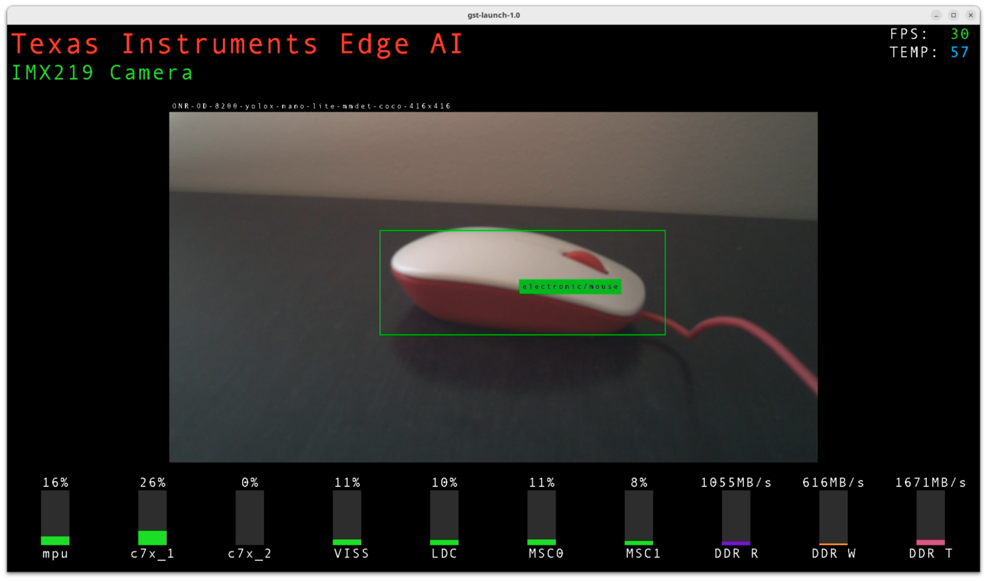
Fig. 152 Object detection demo#
The Edge AI image includes a collection of computer vision demonstrations including object detection and image classification. It enables AM67A SoC features not yet ported to the Beagleboard Debian distribution, including:
AI acceleration using C7x MMA cores
Image signal processing using the VPAC (Vision Processing Accelerator)
Real-time computation on R5F cores
OpenVX + GStreamer orchestration of computer vision pipelines
We will review a few sample GStreamer flows for UDP streaming, object detection, and image pre-processing.
The tutorial concludes with links to additional resources for building a complete Edge AI application of your own.
Hardware setup#
A camera, and a few other additional parts are needed to run Edge AI demos. Optionally, a 3D printed mount can organize the components onto a standard camera tripod with the sensor oriented forward.
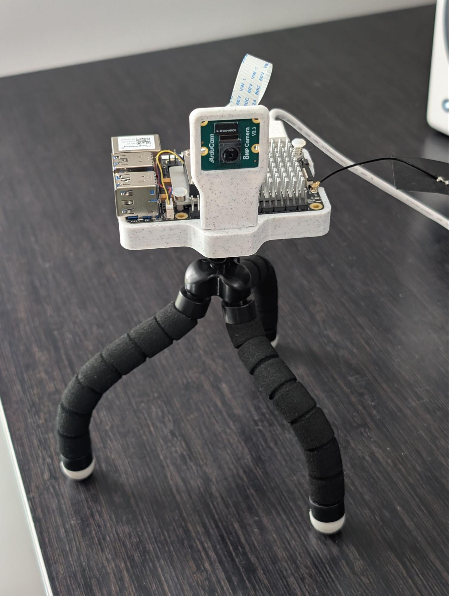
Fig. 153 IMX219 CSI camera module + 3D printed camera mount#
Item |
Notes |
|---|---|
BeagleY-AI |
Pictured with Raspberry Pi 5 Active Cooler |
MicroSD card |
32GB or greater recommended |
Power supply |
|
Camera |
IMX219 CSI module or USB+UVC webcam |
Raspberry Pi debug probe |
For initial device configuration. Learn more here. |
HDMI display |
For interacting with Edge AI GUI |
USB mouse |
For interacting with Edge AI GUI |
3D printed camera mount |
(Optional) For orienting Arducam IMX219 module forward. Download design on Printables. |
Warning
Ensure your power supply provides sufficient wattage (8W+). Powering the device on a laptop USB port may only provide up to 2.5W (0.5A @ 5V).
Important
USB on BeagleY-AI is presently unreliable and often fails to initialize. This issue also impacts Beagleboard Debian. You may observe the USB mouse or camera not being detected.
If you hit this issue, try rebooting the device.
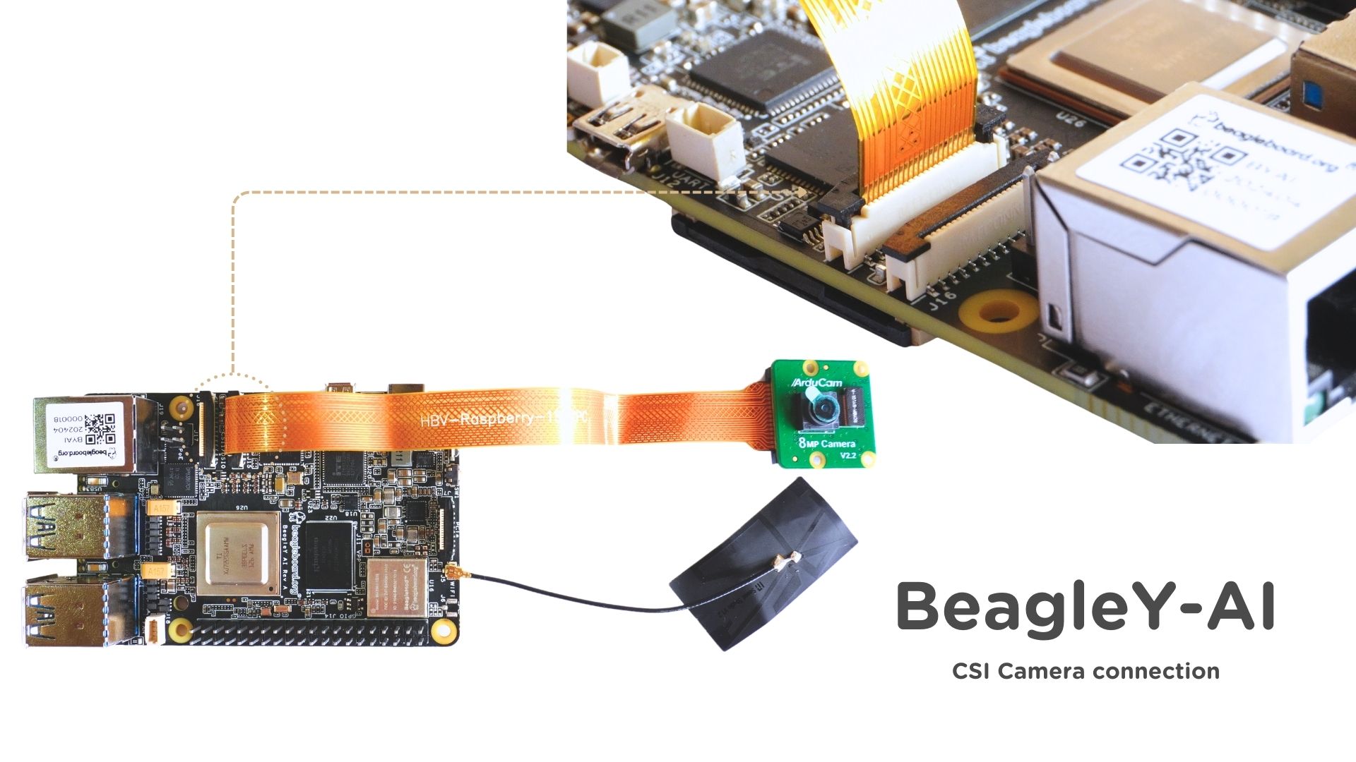
If using an IMX219 camera, connect it to port CSI0 and verify
that the cable leads are oriented correctly.
SD card image#
We require the TI Edge AI for BeagleY-AI image flashed to an SD card for this tutorial. This is a modified version of the official TI Edge AI release with a few device tree and driver additions required for board support of the BeagleY-AI.
Release |
Notes |
|---|---|
11.00.00.08 2025-09-06 (Latest) |
cc33xx driver updated to 1.0.2.10 improving Wi-Fi latency |
cc33xx (Wi-Fi/Bluetooth) 1.0.0.8 driver added |
|
Original BeagleY-AI board support release |
For more information on this image:
Image configuration#
With the SD card flashed and inserted into the BeagleY-AI, it’s time to boot the board and configure it via the debug probe + serial console.
Connecting over serial#
Ensure the host machine is physically connected to the BeagleY-AI’s port via the debug probe.
Then, identify the serial console’s /dev handle and connect using the serial client of your choice
such as minicom.
sudo minicom -con -D /dev/ttyACM0
Tip
Minicom’s -con option enables colors.
Once the BeagleY-AI is booted and you see a login shell in the console, log in as user root. No password is required.
Network configuration#
Connecting the BeagleY-AI to the network will allow us to SSH into the device to remotely develop apps using VSCode over SSH, and stream video to a remote server.
If the device is connected to your router via Ethernet, it should already be connected (try ping google.com).
If you’re using Wi-Fi, we’ll need to configure the device to auto-connect on boot.
Tip
For optimal networking performance, use an Ethernet connection.
While Wi-Fi works, you may notice small delays when typing over an SSH terminal, or frame drops when streaming over UDP. The Beagleboard Wi-Fi cc33xx module driver is new and under active development from TI.
Setting up Wi-Fi#
Execute the following commands to connect to your local Wi-Fi 2.4GHz network.
wpa_passphrase "YOUR_SSID_HERE"
You will be prompted to enter your Wi-Fi password into stdin. Then copy the network={...} output.
Paste this output into a wpa_supplicant conf file that will be read to auto-connect on boot:
sudo mkdir /etc/wpa_supplicant
sudo vi /etc/wpa_supplicant/wpa_supplicant-wlan0.conf
Now, enable the wlan0 service.
systemctl enable --now wpa_supplicant@wlan0.service
Wait a few seconds for your device to connect. Then verify the connection.
ping google.com
Assigning a static local IP#
Later, we will SSH into the BeagleY-AI for remote development. This process is simplified if the BeagleY-AI has a consistent IP address on the LAN.
Get the MAC address on the target via the following. (Replace with eth0 if using Ethernet)
cat /sys/class/net/wlan0/address
Then go to your router’s configuration settings to assign the static IP, e.g. 192.168.1.5.
Verify SSH from host#
Restart your device to ensure the assigned IP address is correctly applied. Then from your host machine, confirm SSH behavior via:
ssh root@192.168.1.5
Camera configuration#
You can connect either an IMX219 camera on port CSI0 or a generic USB+UVC webcam.
IMX219 CSI camera#
We’ll need to apply a provided device tree overlay for the IMX219 to be detected.
Important
Ensure your camera module is an IMX219 sensor. Others will not work.
In order to add support for a new sensor you would need to:
Ensure kernel driver is available
Provide ISP tuning for converting RAW sensor data to RGB
Create and apply a device tree overlay
These steps are outside the scope of this tutorial.
sudo vi /run/media/BOOT-mmcblk1p1/uEnv.txt
Update the name_overlays= line by appending the IMX219 overlay path ti/k3-am67a-beagley-ai-csi0-imx219.dtbo. It should be set to the following:
name_overlays=ti/k3-am67a-beagley-ai-edgeai-apps.dtbo ti/k3-am67a-beagley-ai-csi0-imx219.dtbo
Reboot the device. If the camera is initialized successfully, you should see a log upon login like this:
> ssh root@192.168.1.5
IMX219 Camera 0 detected
  device = /dev/video-imx219-cam0
  name = imx219
  format = [fmt:SRGGB8_1X8/1920x1080]
  subdev_id = /dev/v4l-imx219-subdev0
  isp_required = yes
USB+UVC camera#
If you’re connecting a USB+UVC camera, the camera should automatically be detected upon boot. If detected, you’ll see this log upon SSH login.
> ssh root@192.168.1.5
USB Camera 0 detected
    device = /dev/video-usb-cam0
    format = jpeg
USB Camera 1 detected
    device = /dev/video-usb-cam1
    format = jpeg
Running the AI demos#
We’re now ready to run the Texas Instruments Edge AI demos!
If you haven’t already, plug in a compatible HDMI display + USB mouse, and boot the device. After ~10-20 seconds of boot, you should see the following screen:
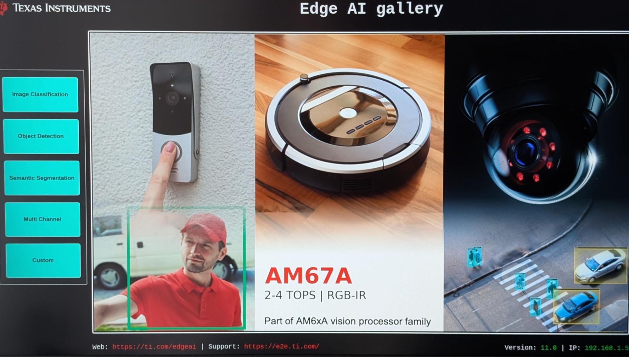
Fig. 154 Edge AI boot screen#
Note
Display port alternatives to HDMI like OLDI/DSI might work but have not been verified.
Use the mouse to select a demo in the side menu.
To test AI inference with the attached camera, click Custom on the left of the home screen. For Input Type, select Camera. For the Camera input, select IMX219 Camera 0 or your attached camera. Then select any vision model to run, and click Start.
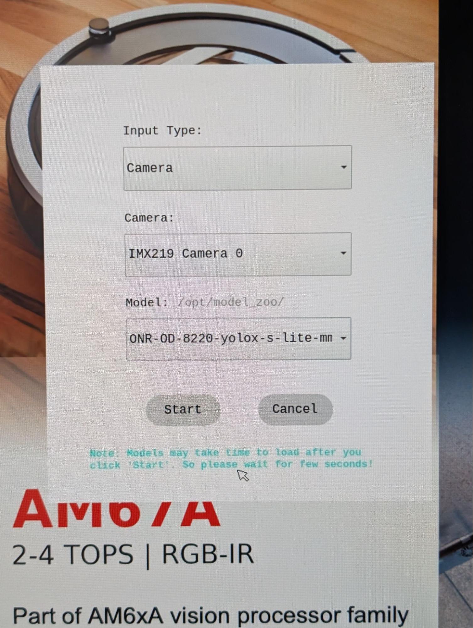
Tip
If the camera is not listed in the drop-down, it may not be configured correctly. Inspect kernel logs at boot, and review camera configuration steps.
Congratulations! We are now utilizing an attached camera, image signal processor, and AI accelerator for a vision application. See TI Edge AI sample apps documentation for more details on the available demos.
Fig. 155 YoloX object detection demo#
Custom vision pipelines with GStreamer#
Under the hood#
Now that we’ve seen what the BeagleY-AI can do, you may be looking to build a vision application of your own. To do that, let’s look under the hood to see how the demos work.
The Edge AI image is a minimal Yocto built image based on the TI Arago project.
On boot, it starts a /usr/bin/edgeai-gui-app -platform linuxfb process (see edgeai-gui-app)
allowing you to graphically interact with a collection of GStreamer examples.
GStreamer is used to orchestrate a multi-stage video pipeline. The pipeline begins with a source element such as a video file or camera feed, passes through various processing elements, and completes at one or more sink elements for export. A sink could be an attached display, output file, or UDP stream.
On the Edge AI image, TI extends GStreamer with a suite of plug-ins (edgeai-gst-plugins) to expose hardware acceleration of image processing, video encoding, and AI inference.
Tip
For a full list of TI provided GStreamer plug-in elements, use the gst-inspect-1.0 command:
root@j722s-evm:/opt/edgeai-gst-apps# gst-inspect-1.0 tiovx

  tiovxcolorconvert: TIOVX ColorConvert
  tiovxdelay: TIOVX Delay
  tiovxdemux: TIOVX Demux
  tiovxdlcolorconvert: TIOVX DL ColorConvert
  tiovxdlpreproc: TIOVX DL PreProc
  tiovxdof: TIOVX DOF
  tiovxdofviz: TIOVX DofViz
  tiovxisp: TIOVX ISP
  tiovxldc: TIOVX LDC
  tiovxmemalloc: TIOVX Mem Alloc
  tiovxmosaic: TIOVX Mosaic
  tiovxmultiscaler: TIOVX MultiScaler
  tiovxmux: TIOVX Mux
  tiovxpyramid: TIOVX Pyramid
  tiovxsde: TIOVX Sde
  tiovxsdeviz: TIOVX SdeViz

root@j722s-evm:/opt/edgeai-gst-apps# gst-inspect-1.0 ti

  ticolorconvert: TI Color Convert
  tidlinferer: TI DL Inferer
  tidlpostproc: TI DL PostProc
  tidlpreproc: TI DL PreProc
  timosaic: TI Mosaic
  tiperfoverlay: TI Perf Overlay
  tiscaler: TI Scaler
There are also a set of video encoder/decoder elements including v4l2h264enc and v4l2h264dec
that are hardware accelerated.
GStreamer provides a high-level abstraction for hardware accelerators so you can quickly create new vision pipelines, often without writing any code. The GStreamer plug-ins are built on a stack of rootfs libraries, kernel drivers, and firmware maintained by TI. It’s a bit complex, and part of why Beagleboard Debian does not yet support hardware acceleration to the same extent as the Edge AI image.
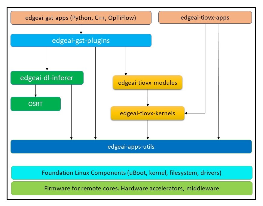
Fig. 156 TI GStreamer plug-in dependencies#
“Hello, camera”#
Let’s create a basic GStreamer vision pipeline of our own, starting with showing what the camera sees on the display. First, stop the default GUI app so it doesn’t interfere:
killall edgeai-gui-app
The following command creates a pipeline with an IMX219 v4l2src source,
a tiovxisp element for processing RAW image data to RGB, and a
autovideosink sink to show the image on the attached display:
gst-launch-1.0 -vvv \
  v4l2src device=/dev/video-imx219-cam0 io-mode=5 ! \
  queue leaky=2 ! \
  video/x-bayer, width=1920, height=1080, format=rggb ! \
  tiovxisp \
    sensor-name=SENSOR_SONY_IMX219_RPI \
    dcc-isp-file=/opt/imaging/imx219/linear/dcc_viss_1920x1080.bin \
    format-msb=7 \
    sink_0::dcc-2a-file=/opt/imaging/imx219/linear/dcc_2a_1920x1080.bin \
    sink_0::device=/dev/v4l-imx219-subdev0 ! \
  video/x-raw, format=NV12 ! \
  autovideosink
The tiovxisp element is a Texas Instruments provided plug-in exposing
access to the onboard ISP (Image Signal Processor). You’ll notice there are
IMX219-specific binaries provided to aid the ISP in providing
a calibrated image.
Note
See the AM6xA ISP Tuning Guide for more information on ISP calibration.
If using a USB camera, it most likely has an integrated ISP you can omit that element from the pipeline:
gst-launch-1.0 -vvv \
  v4l2src device=/dev/video-usb-cam0 io-mode=5 ! \
  video/x-raw, width=1920, height=1080, format=YUY2 ! \
  autovideosink
To see all available resolution/framerates available for your camera, use the v4l2-ctl command:
v4l2-ctl --device /dev/video-usb-cam0 --list-formats-ext
Todo
USB cameras often support video/x-h264 video with higher framerates than video/x-raw.
Add GStreamer pipeline example.
Camera control#
Here are a few GStreamer snippets for altering the image from the camera.
Image orientation#
Depending on your assembly, the image from the IMX219 may not be oriented correctly. For example, the 3D printed mount orients the sensor rotated 180 degrees off.
We can correct this efficiently using the on-board LDC (Lens Distortion Correction). As with other
vision hardware accelerators, this is available via a GStreamer element: tiovxldc.
The following corrects the image by rotating it 180 degrees (inverting X+Y).
gst-launch-1.0 -vvv \
  v4l2src device=/dev/video-imx219-cam0 io-mode=5 ! \
  queue leaky=2 ! \
  video/x-bayer, width=1920, height=1080, format=rggb ! \
  tiovxisp \
    sensor-name=SENSOR_SONY_IMX219_RPI \
    dcc-isp-file=/opt/imaging/imx219/linear/dcc_viss_1920x1080.bin \
    format-msb=7 \
    sink_0::dcc-2a-file=/opt/imaging/imx219/linear/dcc_2a_1920x1080.bin \
    sink_0::device=/dev/v4l-imx219-subdev0 ! \
  tiovxldc \
    sensor-name=SENSOR_SONY_IMX219_RPI \
    warp-params="<-4096, 0, 0, -4096, 15360, 8640>" ! \
  video/x-raw, format=NV12 ! \
  autovideosink
Note
The derivation of warp-params is somewhat complicated, but it defines an affine transformation.
Input image:
  x -> [0 .. 1920]
  y -> [0 .. 1080]

warp-params = [[a, b, c], [d, e, f]] = [a, d, b, e, c, f]
x_aff = a * x + b * y + c
y_aff = d * x + e * y + f

For invert X + Y:
a = -1
b = 0
c = 1920
d = 0
e = -1
f = 1080

a, b, d, e -> S16Q12 (signed number on 14 bits, 2 bits integer + 12 bits fraction)
c, f -> S16Q3 (signed number on 16 bits, 13 bits integer + 3 bits fraction)

a = -1 * 2 ^ 12 = -4096
b = 0
c = 1920 * 2 ^ 3 = 15360
d = 0
e = -1 * 2 ^ 12 = -4096
f = 1080 * 2 ^ 3 = 8640

warp-params = <-4096, 0, 0, -4096, 15360, 8640>
See AM67A datasheet for full details.
Exposure#
If auto-exposure isn’t behaving as you’d like, you can disable it by appending
sink_0::ae-mode=1 to the tiovxisp element:
gst-launch-1.0 -vvv \
  v4l2src device=/dev/video-imx219-cam0 io-mode=5 ! \
  queue leaky=2 ! \
  video/x-bayer, width=1920, height=1080, format=rggb ! \
  tiovxisp \
    sensor-name=SENSOR_SONY_IMX219_RPI \
    dcc-isp-file=/opt/imaging/imx219/linear/dcc_viss_1920x1080.bin \
    format-msb=7 \
    sink_0::dcc-2a-file=/opt/imaging/imx219/linear/dcc_2a_1920x1080.bin \
    sink_0::device=/dev/v4l-imx219-subdev0 \
    sink_0::ae-mode=1 ! \
  video/x-raw, format=NV12 ! \
  autovideosink
Then run this v4l2-ctl command to manually adjust exposure:
v4l2-ctl -d /dev/v4l-imx219-subdev0 --set-ctrl exposure=100
See max and min exposure values:
v4l2-ctl -d /dev/v4l-imx219-subdev0 --list-ctrls
UDP streaming#
True to its name, GStreamer can stream h264 encoded video over UDP so you can view the camera feed remotely.
For this example, you’ll need to install GStreamer on a host machine to preview the output.
UDP server#
On your host machine with GStreamer installed, run:
gst-launch-1.0 -vvv \
  udpsrc port=5000 caps="application/x-rtp, media=video, clock-rate=90000, encoding-name=H264" ! \
  rtph264depay ! avdec_h264 ! videoconvert ! autovideosink
This opens an UDP server expecting h264 video on port 5000.
UDP client#
On your target machine (BeagleY-AI), run:
gst-launch-1.0 -vvv \
  v4l2src device=/dev/video-imx219-cam0 io-mode=5 ! \
  queue leaky=2 ! \
  video/x-bayer, width=1920, height=1080, format=rggb ! \
  tiovxisp \
    sensor-name=SENSOR_SONY_IMX219_RPI \
    dcc-isp-file=/opt/imaging/imx219/linear/dcc_viss_1920x1080.bin \
    format-msb=7 \
    sink_0::dcc-2a-file=/opt/imaging/imx219/linear/dcc_2a_1920x1080.bin \
    sink_0::device=/dev/v4l-imx219-subdev0 \
    sink_0::ae-mode=1 ! \
  video/x-raw, format=NV12 ! \
  tiovxldc \
    sensor-name=SENSOR_SONY_IMX219_RPI \
    warp-params="<-4096, 0, 0, -4096, 15360, 8640>" ! \
  video/x-raw,format=NV12, width=1920, height=1080 ! \
  v4l2h264enc extra-controls="controls, frame_level_rate_control_enable=1, video_bitrate=10000000, video_gop_size=30" ! \
  h264parse ! rtph264pay ! udpsink host=192.168.1.18 port=5000 sync=false
Note
Replace 192.168.1.18 with the local IP address of the host machine.
If successfully connected, a video preview should appear on your host machine.
This pipeline leverages the hardware-backed h264 video encoder via v4l2h264enc.
Object detection#
Let’s bring it all together in an object detection example.
This pipeline uses tiovxmultiscaler to create a branch for AI inference.
It resizes the image down to 416x416, processes the image with tiovxdlpreproc
and tidlinferer, and overlays the detections on the original image with
tidlpostproc.
Building on previous examples, it processes IMX219 with the ISP, rotates the image, and streams the output to a UDP server.
gst-launch-1.0 -vvv \
  v4l2src device=/dev/video-imx219-cam0 io-mode=5 ! \
  queue leaky=2 ! \
  video/x-bayer, width=1920, height=1080, format=rggb ! \
  tiovxisp \
    sensor-name=SENSOR_SONY_IMX219_RPI \
    dcc-isp-file=/opt/imaging/imx219/linear/dcc_viss_1920x1080.bin \
    format-msb=7 \
    sink_0::dcc-2a-file=/opt/imaging/imx219/linear/dcc_2a_1920x1080.bin \
    sink_0::device=/dev/v4l-imx219-subdev0 sink_0::ae-mode=1 ! \
  video/x-raw, format=NV12 ! \
  tiovxldc \
    sensor-name=SENSOR_SONY_IMX219_RPI warp-params="<-4096, 0, 0, -4096, 15360, 8640>" ! \
  video/x-raw, format=NV12 ! \
  tiovxmultiscaler \
    name=split_01 src_0::roi-startx=0 src_0::roi-starty=0 src_0::roi-width=1920 src_0::roi-height=1080 target=0 split_01. ! \
  queue ! \
  video/x-raw, width=480, height=416 ! \
  tiovxmultiscaler target=1 ! \
  video/x-raw, width=416, height=416 ! \
  tiovxdlpreproc model=/opt/model_zoo/ONR-OD-8200-yolox-nano-lite-mmdet-coco-416x416 out-pool-size=4 ! \
  application/x-tensor-tiovx ! \
  tidlinferer target=1 model=/opt/model_zoo/ONR-OD-8200-yolox-nano-lite-mmdet-coco-416x416 ! \
  post_0.tensor split_01. ! \
    queue ! \
    video/x-raw, width=1920, height=1080 ! \
    post_0.sink tidlpostproc name=post_0 \
      model=/opt/model_zoo/ONR-OD-8200-yolox-nano-lite-mmdet-coco-416x416 \
      alpha=0.200000 viz-threshold=0.600000 top-N=5 display-model=true ! \
    queue ! \
    v4l2h264enc extra-controls="controls, frame_level_rate_control_enable=1, video_bitrate=10000000, video_gop_size=30" ! \
    h264parse ! rtph264pay ! udpsink host=192.168.1.18 port=5000 sync=false
There are many more detailed examples on the Edge AI image in the /opt/edgeai-gst-apps directory. Documentation on these
examples are available in the TI Edge AI sample apps documentation.
Next steps#
The Edge AI image serves as a demonstration of the vision and AI capabilities of the AM67A. Additionally, the Beagleboard port used in this tutorial serves as a reference implementation of required kernel and driver changes needed to support Beagleboards like the BeagleY-AI.
You may be now looking to build a vision app of your own! Your best resource will be the official Texas Instruments Processor SDK Linux AM67A and Edge AI documentation. This includes tutorials on training custom models for your app.
Important
Simple experiments may get away with modifying the demo image.
You can edit the /opt/edgeai-gst-apps examples remotely using VSCode over SSH.
For more complex applications, you may notice limitations of editing a minimal Yocto-built
image. It lacks a package manager like apt from Debian, so new dependencies must be compiled
from source. In this situation, you should consider moving to a Yocto-built image yourself using
TI docs.
In the future, the community may provide additional tutorials to supplement Texas Instruments documentation for tasks like training a model or a Yocto build.
In the meantime, find us in Discord in the #edge-ai channel!
